User:Mcmaster/K2scope
"k2scope"
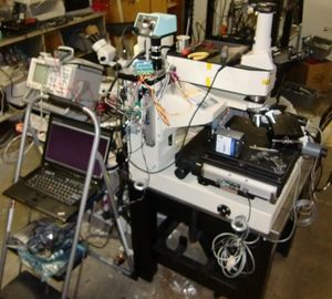
I've acquired 2 or 3 K2 IND systems and have mixed/matched parts to combine them into a working system.
Basically what happened was I tried really hard to get one at local auction but kept getting outbid. I found one at reasonable price on eBay (after some negotiation) and acquired it. However, it didn't come with any objectives. Somehow after this I managed to win a very nice system at industrial auction for pretty low price (lower than the objectives would have cost on eBay). I ultimately had to mix/match parts from the two systems to get good optical quality.
Nikon clamps are 8-32 (revolving nosepiece and such)
Contents
Historical notes
BOM
Given the quality of this system and how much I bid to get other systems, this system has been surprisingly low cost to build.
Combining parts into a working high quality system composed of:
| Image | Vendor | Model | Description | Source system | Notes |
|---|---|---|---|---|---|
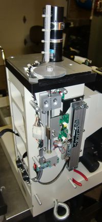
| Zygo / Tech Inst | KMS310RT | Chassis | KMS310RT | base / Z axis | |
| Tech | K2IND-KMS310 | Illuminator | KMS310RT | ||
| Nikon | Lamphouse | KMS310RT | Mercury burner | ||
| Nikon | HB-10103AF | Lamp PS | KMS310RT | Mercury burner PS | |
| Tech Inst? | ? | XY stepper table | Disp Serv XY | ||
| Compumotor | M57-102 | XY stepper driver | Disp Serv XY | ||
| Gecko | G320X | Z servo driver | Gecko | Came with a gecko! | |
| Nikon | CF Plan | Objective | KMS310RT | 10x, 20x, 50x, 100x Missing the 5x, has a slot for it | |
| Nikon | ? | Observation tube, trinocular | Nikon K2 | Original system was binocular | |
| NRC | Model 39 | Tilt correction | eBay | Mirror mount | |
| McMaster | Enclosed pr0ndexer | Indexer | Digikey, Amazon | 2.5 combicon Lovingly assembled | |
| McMaster | pr0nscope | Control software | N/A | ||
| Lenovo | t61p | Control laptop | weird stuff |
Motorized Z axis
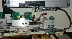
Above: Zygo electronics overview
Have this sort of working using Gecko drive but not very well
| Signal | Encoder wire | Cable wire | Notes |
|---|---|---|---|
| Floating | Shield | Clear unshielded | |
| Common | Black | Black | |
| +5V | White | White | |
| A | Brown | Orange | |
| B | Red | Red | |
| Z | Yellow | N/C | Probably once-per-rev reference mark |
| ? | N/C | Green | ? |
Motor details
Motor: Harmonic Drive "HiT Drive SERVO ACTUATOR, RH-11-6001-E100DO5"
- Encoder (sold with motor): ENCODER-02A 1000P /R
Website] decoding of RH-11-6001-E100DO5:]
- RH Type: RH mini series
- 11 size 11
- 60 Output shaft rated rotational speed (r/min) 60 r/min
- 01 Rated output (W) x10 10 W
- E incremental encoder
- 100 encoder resolution 1000p/r
- D Encoder power supply 5-12
- Case says 5V
- O: open collector
- aha!
- 5: ?
- Not a special suffix
- indicates 5V operation?
Encoder details
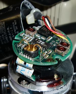
Cover removed:
Glass rotary encoder with open drain outputs.
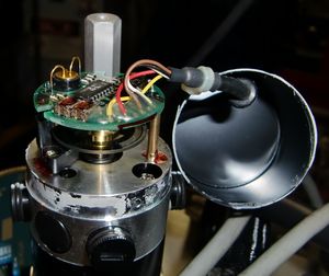
I opened this up because I was having trouble getting signal (2014-09-29) and thought it might have been broken. Now I know it was just an open drain vs actively driven issue.
Above: troubleshooting encoder signals
When I asked Gecko about my linear encoders they didn't seem that familiar with them (which seems a bit odd but w/e). In any case, they recommended the follow qudrature encoders:
- CUI AMT102-V
- US Digital quadrature encoder
Nosepiece
Motor: FRAULHABER
MOTOREN
22BK 40.5:1
Lamphouse
"super high pressure mercury"
Model: Nikon LH-M100CB-1
Use bulb: USH-102DH
Manual]]
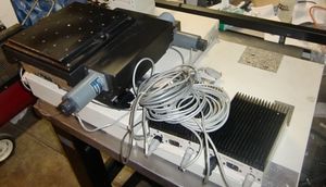
XY stage
Not original stage but roughly footprint compatible
Manual]]
Motor
Model: M57-102
Serial: 27852
Code:
Driver
COMPUMOTOR
CORPORATION
Model: M57-102
Serial: 27852
Code: A
Control cable is a DB-9 to funky female connector
FIXME: think table is wrong. Conflicts with M-Drive appendix C and motor isn't working
| DB-9 pin | Indexer pin | Cable color | Name | Notes |
|---|---|---|---|---|
| 1 | B | Red | STEP+ | |
| 2 | A | Green | DIR+ | |
| 3 | C | Blue | SHUT+ | N/C if unused |
| 4 | F | Brown | SHUT- | N/C if unused |
| 5 | E | Black | DIR- | |
| 6 | D | White | STEP- | |
| N/C? | H |
Driver box
Had a driver box but it got lost in the move.
Trying to troubleshoot why not moving. Notes from a while back
20 mA drive required
"TTL level"
100 ohm resistor + diode
(3.3 V - 0.7V) / 100 = 0.026
Currently using 5V. Is that somehow too much?
Driver boxes are on: motors are locked in place. Any chance the shutdown input got triggered?
Double checked pinout vs above and it sounds like its wired correctly with step/direction
Maybe try switching them if its backwards somehow?
Can't find the k2 stepper config. How many steps per mm?
M-Drive manual has note:
TTL Inputs: 3.5 to 6.0 V pulse height
500 ns pulse width minimum
20 mA minimum current
1 MHz maximum pulse rate
Appendix C
| Pin | Color |
|---|---|
| STEP OUTPUT + | RED |
| STEP OUTPUT - | BLK |
| DIRECTION OUTPUT + | GRN |
| DIRECTION OUTPUT - | WHT |
| SHUTDOWN OUTPUT + | BLU |
| SHUTDOWN RETURN - | BRN |
