Difference between revisions of "Bonder"
| Line 8: | Line 8: | ||
* [[Kulicke & Soffa Industries, Inc.]] | * [[Kulicke & Soffa Industries, Inc.]] | ||
* [[Anza Technology, Inc.]] | * [[Anza Technology, Inc.]] | ||
| + | |||
| + | |||
| + | |||
| + | = Introduction = | ||
| + | |||
| + | Wire bonding is an umbrella term for several different processes which attach wires from the bond pads of an IC die to the package leadframe. | ||
| + | |||
| + | During reverse engineering activities, it is often necessary to [[bonding:removal|remove unwanted bonds]] and/or [[bonding:rebond|re-bond depackaged devices]]. | ||
| + | |||
| + | = Processes = | ||
| + | |||
| + | Several different bonding processes are in common use. These are: | ||
| + | * [[bonding:ball|Thermosonic ball bonding]] | ||
| + | * [[bonding:wedge|Thermosonic wedge bonding]] | ||
| + | |||
| + | = Bond wire materials = | ||
| + | |||
| + | [[wire|Wire main page]] | ||
| + | |||
| + | Wedge bonds are typically gold or aluminum. | ||
| + | |||
| + | Ball bonds were almost always made of gold until fairly recently, but c. 2010 increases in the price of gold caused many companies to begin exploring copper wire bonding due to its lower cost (and electrical resistance). Copper is much more reactive than gold, however, so the process is somewhat more complex since the ball must be formed inside an inert or reducing atmosphere. Typically forming gas (90% N2 / 10% H2) is released from a nozzle near the tip of the capillary and held in place by a cup-shaped shield while the arc is struck. | ||
| + | |||
| + | As a result, copper ball bonders can be used with gold wire (by turning off the supply of shielding gas) but copper wire cannot be used with a bonder originally designed for gold unless a gas shield system is retrofit. | ||
| + | |||
| + | = Wedge bond = | ||
| + | |||
| + | [[File:bond_wedge_bond.jpg|300 px]] | ||
| + | |||
| + | = Ball bond = | ||
| + | |||
| + | [[File:zoidberg_ball_bond_02_neo20x_cropped.jpg|300 px]] | ||
| + | |||
| + | [[File:smithsonian_ball_bond.jpg|300 px]] | ||
| + | |||
| + | Above: source: SI report | ||
| + | |||
| + | |||
| + | = Leadframe bond = | ||
| + | |||
| + | [[File:mcmaster_bonding_leadframe_bond.jpg|300 px]] | ||
| + | |||
| + | Above: a low power device with direct leadframe bonding | ||
| + | |||
| + | IIRC sometimes used on memory devices | ||
| + | |||
| + | |||
| + | = References = | ||
| + | |||
| + | http://extra.ivf.se/ngl/documents/ChapterA/ChapterA2.pdf | ||
Revision as of 00:11, 5 March 2019
Parts:
Vendors:
Contents
Introduction
Wire bonding is an umbrella term for several different processes which attach wires from the bond pads of an IC die to the package leadframe.
During reverse engineering activities, it is often necessary to remove unwanted bonds and/or re-bond depackaged devices.
Processes
Several different bonding processes are in common use. These are:
Bond wire materials
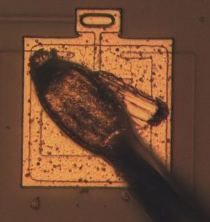
Wedge bonds are typically gold or aluminum.
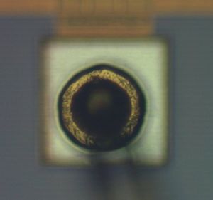
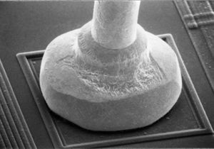
Ball bonds were almost always made of gold until fairly recently, but c. 2010 increases in the price of gold caused many companies to begin exploring copper wire bonding due to its lower cost (and electrical resistance). Copper is much more reactive than gold, however, so the process is somewhat more complex since the ball must be formed inside an inert or reducing atmosphere. Typically forming gas (90% N2 / 10% H2) is released from a nozzle near the tip of the capillary and held in place by a cup-shaped shield while the arc is struck.
As a result, copper ball bonders can be used with gold wire (by turning off the supply of shielding gas) but copper wire cannot be used with a bonder originally designed for gold unless a gas shield system is retrofit.
Wedge bond
Ball bond
Above: source: SI report
Leadframe bond
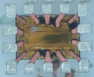
Above: a low power device with direct leadframe bonding
IIRC sometimes used on memory devices


