Difference between revisions of "User:Mcmaster/Pr0ncnc"
(Created page with "pr0ncnc is the standard platform that I use to build my CNC microscopes. A typical system consists of: ** uvscada for high level control ** AmScope MU800 camera ** Driver bo...") |
|||
| Line 1: | Line 1: | ||
| + | [[Category:mcmaster]] | ||
| + | |||
pr0ncnc is the standard platform that I use to build my CNC microscopes. A typical system consists of: | pr0ncnc is the standard platform that I use to build my CNC microscopes. A typical system consists of: | ||
| − | + | * uvscada for high level control | |
| − | + | * AmScope MU800 camera | |
| − | + | * Driver box | |
** BBB running machinekit | ** BBB running machinekit | ||
** BBB cape w/ optional CD4050 3.3V => 5V boosters | ** BBB cape w/ optional CD4050 3.3V => 5V boosters | ||
| − | + | *** XYZ output standard | |
** Connected over USB w/ static USB-ethernet bridge IP | ** Connected over USB w/ static USB-ethernet bridge IP | ||
** Case: Hammond 1591-E | ** Case: Hammond 1591-E | ||
** TODO: standard rubber feet | ** TODO: standard rubber feet | ||
| − | + | * IMS MDrive stepper motors (such as MDrive17 or MDrive23) | |
| − | + | * Linear stages vary | |
| − | + | * Step/direction connectors: Combicon 4 pin | |
** TODO: move to mini connectors | ** TODO: move to mini connectors | ||
| − | + | * Where applicable, bipolar motors use Combicon 5 pin | |
| − | + | * Newport 39 mirror mount (tip tilt stage) | |
BBB bolt pattern | BBB bolt pattern | ||
| − | + | * WARNING: not square. According to breakout.py: | |
** 0.000, 0.000 | ** 0.000, 0.000 | ||
** 0.000, 1.900 | ** 0.000, 1.900 | ||
** 2.600, 0.125 | ** 2.600, 0.125 | ||
** 2.600, 1.775 | ** 2.600, 1.775 | ||
| − | + | * For 4-40 standoffs into case | |
| − | + | * Standoffs are CA glued in | |
| − | + | * Standoffs should not peek out other side | |
| − | + | * Consider putting Kapton on back in case they stick through slightly | |
| − | + | * Need tight fit. Drill size? | |
= Motor connector = | = Motor connector = | ||
| Line 38: | Line 40: | ||
Cable colors | Cable colors | ||
| − | + | * Step+: red (left) | |
| − | + | * Step-: black | |
| − | + | * Dir+: blue | |
| − | + | * Dir-: white (right) | |
= BBB 5V cape = | = BBB 5V cape = | ||
| Line 49: | Line 51: | ||
Based on CRAMPS pinout | Based on CRAMPS pinout | ||
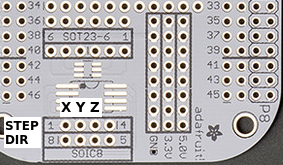
| − | [File:mcmaster_brainscope_bbb_breakout_5v.png] | + | [[File:mcmaster_brainscope_bbb_breakout_5v.png]] |
P8 | P8 | ||
{| class="wikitable sortable" border=1 | {| class="wikitable sortable" border=1 | ||
| − | ! Pin !! CPU GPIO !! CNC function !! I/O !! Color !! Note | + | ! Pin !! CPU GPIO !! CNC function !! I/O !! Color !! Note | |
|- | |- | ||
| − | | 12 || gpio1[12] || X dir || O || White || | + | | 12 || gpio1[12] || X dir || O || White || |
|- | |- | ||
| − | | 13 || gpio0[23] || X step || O || Blue || | + | | 13 || gpio0[23] || X step || O || Blue || |
|- | |- | ||
| − | | 14 || gpio0[26] || Y dir || O || White || | + | | 14 || gpio0[26] || Y dir || O || White || |
|- | |- | ||
| − | | 15 || gpio1[15] || Y step || O || Blue || | + | | 15 || gpio1[15] || Y step || O || Blue || |
|- | |- | ||
| − | | 18 || gpio2[1] || Z dir || O || White || | + | | 18 || gpio2[1] || Z dir || O || White || |
|- | |- | ||
| − | | 19 || gpio0[22] || Z step || O || Blue || | + | | 19 || gpio0[22] || Z step || O || Blue || |
|- | |- | ||
|} | |} | ||
| Line 72: | Line 74: | ||
Colors | Colors | ||
| − | + | * Dir: white | |
| − | + | * Step: blue | |
I'd like to stick with 5 V CMOS style outputs since all my units can take those | I'd like to stick with 5 V CMOS style outputs since all my units can take those | ||
| − | + | * Traditional drivers are optocopulers and take resistor limited +/- 5V inputs | |
| − | + | * MDrive17, MDrive23 basically 5-24V open drain but can also operate CMOS | |
IMS MDrive probably don't take much current (TODO: verify) | IMS MDrive probably don't take much current (TODO: verify) | ||
| Line 84: | Line 86: | ||
My Compumotor M-Drive requires 20 mA min | My Compumotor M-Drive requires 20 mA min | ||
| − | + | * CD4050 can typically only source 3 mA or so | |
| − | + | * HEF4050 can do 20 mA max…borderline | |
| − | + | * Sparkfun BOB-12009 theoretically can do 220 mA | |
Originally I shied away from the BOB, but think I can simplify the soldering process to make it more attractive | Originally I shied away from the BOB, but think I can simplify the soldering process to make it more attractive | ||
| Line 106: | Line 108: | ||
Place V4L control values into microscope.json | Place V4L control values into microscope.json | ||
| − | + | * see example configs for specific usage | |
Revision as of 02:09, 5 March 2019
pr0ncnc is the standard platform that I use to build my CNC microscopes. A typical system consists of:
- uvscada for high level control
- AmScope MU800 camera
- Driver box
- BBB running machinekit
- BBB cape w/ optional CD4050 3.3V => 5V boosters
- XYZ output standard
- Connected over USB w/ static USB-ethernet bridge IP
- Case: Hammond 1591-E
- TODO: standard rubber feet
- IMS MDrive stepper motors (such as MDrive17 or MDrive23)
- Linear stages vary
- Step/direction connectors: Combicon 4 pin
- TODO: move to mini connectors
- Where applicable, bipolar motors use Combicon 5 pin
- Newport 39 mirror mount (tip tilt stage)
BBB bolt pattern
- WARNING: not square. According to breakout.py:
- 0.000, 0.000
- 0.000, 1.900
- 2.600, 0.125
- 2.600, 1.775
- For 4-40 standoffs into case
- Standoffs are CA glued in
- Standoffs should not peek out other side
- Consider putting Kapton on back in case they stick through slightly
- Need tight fit. Drill size?
Contents
Motor connector
Although there is a de-facto DB25 standard for step/direction pulses (from Compumotor?), I don't like DB25 connectors. Instead I use Combicon connectors since I can quickly wire them up and plug/unplug them.
- 29 drill for panel mount Combicon bolt holes using 6-32 SHCS
Cable colors
- Step+: red (left)
- Step-: black
- Dir+: blue
- Dir-: white (right)
BBB 5V cape
Defunct: I now use b3index
Based on CRAMPS pinout
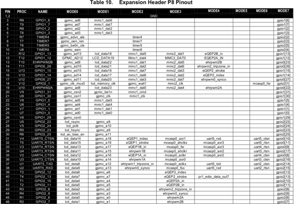
P8
| Pin | CPU GPIO | CNC function | I/O | Color | |
|---|---|---|---|---|---|
| 12 | gpio1[12] | X dir | O | White | |
| 13 | gpio0[23] | X step | O | Blue | |
| 14 | gpio0[26] | Y dir | O | White | |
| 15 | gpio1[15] | Y step | O | Blue | |
| 18 | gpio2[1] | Z dir | O | White | |
| 19 | gpio0[22] | Z step | O | Blue |
Colors
- Dir: white
- Step: blue
I'd like to stick with 5 V CMOS style outputs since all my units can take those
- Traditional drivers are optocopulers and take resistor limited +/- 5V inputs
- MDrive17, MDrive23 basically 5-24V open drain but can also operate CMOS
IMS MDrive probably don't take much current (TODO: verify)
My Compumotor M-Drive requires 20 mA min
- CD4050 can typically only source 3 mA or so
- HEF4050 can do 20 mA max…borderline
- Sparkfun BOB-12009 theoretically can do 220 mA
Originally I shied away from the BOB, but think I can simplify the soldering process to make it more attractive
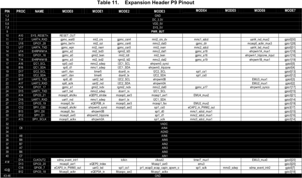
BBB pinout
Camera calibration
Put white piece of paper under camera
Run manbal.py to get RGB values
Adjust V4L controls until balanced
Place V4L control values into microscope.json
- see example configs for specific usage
Combicon misc
Pin 1 on the left when
- Female: looking in with round side down
Motor cables
Use 5 pos combicon for bipolar motors (wires: 2 A, 2 B, GND)
BOM
- Molex 1552200235 (Digikey WM15664-10-ND)
- Phoenix Contact 1786200 (Digikey 277-5776-ND)
- Phoenix Contact 5448640 (Digikey 277-11353-ND)
Notes:
- 6' cables
- Cut sheath 2" from ends
- Expose wire 3/8"
- 3" of heatshrink (think its 1/2")
Pins (ordered by color code):
- 1 Black
- 2 Brown
- 3 Green
- 4 Blue
- 5 White
Power cables
Two position combicon
Pins (ordered by color code):
- 1 Black
- 2 Red


