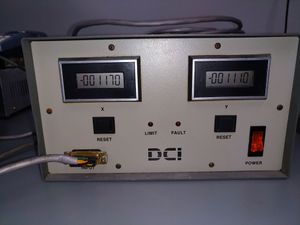
DCI Drive
DCI stepper motor driver.
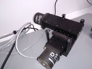
Stage
The provided stage. Marked "DCI MC-001".
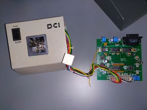
Joystick
The stage is meant to be manually controlled via a joystick.
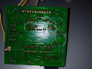
The joystick module is a 2-layer PCB which generates step/direction pulses using one CD4046B PLL IC for each axis. This is clearly a prototype or low-volume product given that there are at least four obvious pieces of rework on the board.
Drive
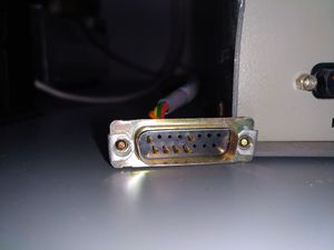
The drive unit accepts step/direction pulses on a DA-15 D-sub connector. Only six of the 15 positions are loaded, configured as follows. All signals are 5V CMOS logic levels.
| Pin number ! Wire color ! Function | Black | Ground | Orange | +10V power to joystick | Yellow | X axis step | Green | Y axis step | Red | X axis direction | Brown | Y axis direction |
|---|
TODO: internal photos of the drive unit, back panel, etc
