User:Mcmaster/Brainscope
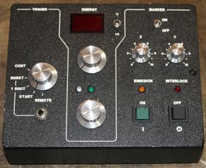
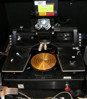
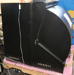
Mitutoyo / Micromanipulator probe station with EZLAZE laser
Contents
Condition
The following issues have been noted:
- EZLAZE: PS missing
- XY stage: missing X motor and maybe some related brackets
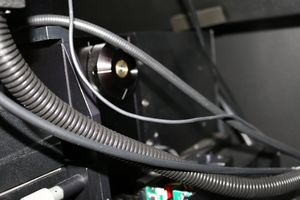
- FS-60: possibly missing part…fine focusing knob?
- FS-60: focusing knob fell off (during shipping I think)
- Broken e-stop wire (from dissassembly?)
- Misc rusted screws. Rust has not been found on anything critical
EZLAZE
Head
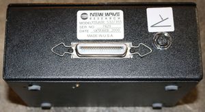
NEW WAVE
RESEARCH
MODEL EZLAZE 532/355
SER NO XXX
DATE OCTOBER 2000
MADE IN USA
US Patent 5,611,946
Power supply
Power supply missing
Above: power supply this unit should take [eBay ntxsupply item 151675355993]
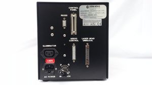
Console
Camera
Genwac
GW-202B
Microscope
Mituotyo Finescope, likely FS-60
Above: focus knob
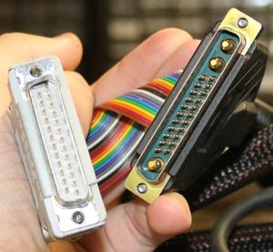
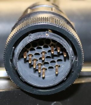
Above: likely motorized stage power/control connector
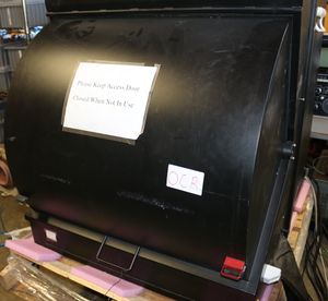
Hood
For doing optical emission analysis. Also good to block out dust in my dusty garage
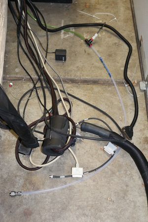
Above: misc cables hanging out of the hood going to the various electronics inside
2015-08-16
Removed hood to move to proper table and overhaul control system. Notes:
- ezlaze is not water cooled
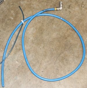
- water cooling is for chuck
- BNC connector bent
- From move?
- CPC for thermal chuck (not motors)
- Motors are synchronous stepping
- Replacing with IMS NEMA 23
Motor
IMS MDM1FSD23A7
NEMA 23
"These are 90 oz/in"
Closest match: step/direction input version
- Datasheet]]
- Spec sheet]]
- MDMXXX174
- MDrive 17 Plus step and direction input
- SPI
Y axis test
| Color | Signal | To |
| White | Optocoupler reference | BBB P9.5-6 5V Red |
| Orange | Step | BBB P8.15 Blue |
| Blue | Direction | BBB P8.14 White |
| Brown | Output bridge enable | N/C |
| Black | Ground | Ground Black |
| Red | Power 12-75 VDC |
24V |
Open question: do I need the programming cable?
- I think I have one
Initial current draw 50 mA. Holding torque is not very good; slightly above off level. Spikes to around 80 mA at startup
BBB: mk-test. Verified powers up
changes 10 mA (min PS resolution) when try to move. Time to play with settings cable
Cable: MD-CC4 USB to RS422 Comm Converter
Unfortunately:
The MDrive microstepping integrated motor and driver use the Serial
Peripheral Interface (SPI) to configure the setup parameters.
Use bus pirate or beagle
2015-08-17
Decided to try one last time to see if I could move motors before messing with programming cables.
Hooked up a test motor without any shaft load. Spins fine and has reasonable torque.
Hooked Y2 axis back up and was able to move it just fine. Issues yesterday evidently were just due to shoddy wiring
Conclusion: don't need programming cable. Default settings seem to be good enough for now
Also validates that motors are good enough. Need to get 1-2 more for XY1. Wait until I take it apart to verify clearances etc?
X2 motor won't fit:
- original: 2.0"
- max: 2.2"
- mine: 2.7" (official IMS docs list Lmax: 2.65")
Looked around and it looks like its going to be difficult to find any motors with integrated drivers at this constrained size. Min length from vendors:
- IMS: 2.65"
- linengineering: 2.69"
- anaheimautomation: 2.98"
Time to see if I can make these motors work. I have some reasonably compact standalone IMS drivers (by coincidence also IMS) I can try to use
http://www.cnczone.com/forums/stepper-motors-drives/15273-slo-syn-motor-wiring-info.html]]
- 4 wire motors are bipolar
- 5 wire motors are unipolar
- 6 or 8 wire motors can be wired either way
Mine: 6 wire
- Red
- White-red
- Green
- White-green
- White
- Black
In stock:
- 3x IMS INT-481]]
- 4x Compumotor OEM650]]
2015-08-20
Briefly poked at things. Current plan:
- Try to use original motors. This is combination of tight clearance in X2 combined with advantages of using existing wiring harness in X1/Y1
- See if I can get INT-481 to work with the slo-syn motors?
- A fourth INT-481 may cost $100
- This makes OEM650 more attractive since I have more of them
- They are slightly bigger but also easier to mount
- Z1 axis is a NEMA 34 motor. Does not appear to be a slo-syn. Maybe compumotor
- Low priority
- Make a schematic
- Fix e-stop loose wire (after schematic to better understand where it should go)
2015-08-21
Working on schematic
Back connectors
Electrical:
- (STAGE): 25×2 0.1" male IDC
- T/C: type K thermocouple plug
- HEATER: 4 pin CPC twist lock
Pnematic:
- VACUUM
- STAGE IN
- STAGE OUT
- RING IN
- RING OUT
What is RING?
X1 ribbon cable
Main board: J2
Breakout board: Y
| Y1 pin | 50 pin | Function | Notes |
|---|---|---|---|
| 1 | 28 | ||
| 2 | 21 | ||
| 3 | N/C | ||
| 4 | N/C | ||
| 5 | 22 | ||
| 6 | 19 | ||
| 7 | 27 etc | ||
| 8 | N/C | ||
| 9 | N/C | ||
| 10 | 5 | ||
| 11 | 2 | ||
| 12 | 3 | ||
| 13 | 6 | ||
| 14 | 4 |
Main board
I did not pin this out directly since I don't need to interface it directly
Connectors:
| J | Label | Notes |
|---|---|---|
| 1 | ||
| 2 | X | X1 motor, limit |
| 3 | Y | Y1 motor, limit |
| 4 | Z-ROT | N/C |
| 5 | Z-LIM | Into chassis |
| 6 | Z-MOT | Directly to NEMA 34 motor |
| 7 | THETA | N/C |
| 8 | - | X1 limit? |
| 9 | - | estop |
Y1 ribbon cable
Main board: J3
Breakout board: Y
| X1 pin | 50 pin | Function | Notes |
|---|---|---|---|
| 1 | 29 |
||
| 2 | 23 | ||
| 3 | N/C | ||
| 4 | N/C | ||
| 5 | 24 | ||
| 6 | 19 | ||
| 7 | 20 27 29 |
||
| 8 | N/C | ||
| 9 | 7 | ||
| 10 | 11 | ||
| 11 | 8 | ||
| 12 | 9 | ||
| 13 | 12 | ||
| 14 | 10 |
Y1 motor
Dataplate:
Superior Electric
SLO-SYN
SYNCHRONOUS/STEPPING MOTOR
TYPE: M061-LS02
OZ. IN: HOLD 60
RPM: SPEC BM101025
STEPS: 200
V: 5.0
A: 1.0
HZ: DC
CLASS A INSULATION
IMPEDANCE PROTECTED
X1 is probably identical
With breakout board rightside up pin 1 is at P2 right (on silkscreen)
| P2 pin | Color | Function | Notes |
|---|---|---|---|
| 1 | Green | A1 | |
| 2 | White | AC | |
| 3 | White-red | B1 | |
| 4 | Black | BC | |
| 5 | Red | B2 | |
| 6 | White-green | A2 |
X1, Y1 breakout board
ASSY A1003958
has following connectors:
- Y : "Y ribbon cable"
- Upper right pin 1: on silkscreen and agrees with convention I was already using
- Both X and Y board have label Y
- P1: N/C. Ignore for now?
- P2: motor. Has thicker traces
- P3: limit switches?
| Y pin | To | Function | Notes |
|---|---|---|---|
| 1 | P1.2 | ||
| 2 | P3.3 | ||
| 3 | P3.4 | ||
| 4 | P3.6 | ||
| 5 | P3.5 | ||
| 6 | P1.4 P3.1 |
||
| 7 | P1.3 P3.2 |
||
| 8 | N/C | ||
| 9 | P2.1 | ||
| 10 | P2.6 | ||
| 11 | P2.2 | ||
| 12 | P2.5 | ||
| 13 | P2.3 | ||
| 14 | P2.4 |
e-stop (white, black)
All are N/C
| Pin | 50 pin | Color | Function | Notes |
|---|---|---|---|---|
| 1 | 47 | White | Broken button side | |
| 2 | 48 | Black | ||
| 3 | 49 | N/C | ||
| 4 | 50 | N/C |
e-stop (green, blue)
to heater connector
HEATER
| Pin | Color | Function | Notes |
|---|---|---|---|
| Green | e-stop | ||
| Blue | e-stop | ||
| Black | chuck power | ||
| White | chuck power |
Goes to large loose brown connector near wafer chuck
VACUUM
Goes to t junction near front panel
- To vacuum gauge
- To switch
Not sure where goes from switch
I don't currently need the vacuum system but have no reason to rip it out. Leave it for now
Hoses could potentially tangle into Z1 drive but I could secure them if I eventually use Z1
THETA
Main board: J7
| Pin | 50 pin | Function | Notes |
|---|---|---|---|
| 1 | N/C | ||
| 2 | 43 | ||
| 3 | 19 | ||
| 4 | 44 | ||
| 5 | 20 27 31 |
||
| 6 | N/C | ||
| 7 | N/C | ||
| 8 | N/C | ||
| 9 | 35 | ||
| 10 | 39 | ||
| 11 | 36 | ||
| 12 | 37 | ||
| 13 | 40 | ||
| 14 | 38 |
Z-LIM
Main board: J5
| Pin | 50 pin | Color | Function | Notes |
|---|---|---|---|---|
| 1 | 26 | Orange | ||
| 2 | 19 | Red | ||
| 3 | 27 etc | Black | ||
| 4 | 25 | Blue | ||
| 5 | 19 | Red | ||
| 6 | 27 etc | Black |
X2?
Main board: J8
| Pin | 50 pin | Color | Function | Notes |
|---|---|---|---|---|
| 1 | 25 | Green | ||
| 2 | 27 etc | Black | ||
| 3 | 31 | Yellow | ||
| 4 | 19 | Red | ||
| 5 | 27 etc | Black | ||
| 6 | 32 | Orange |
Z-ROT
Main board: J4
| Pin | 50 pin | Function | Notes |
|---|---|---|---|
| 1 | N/C | ||
| 2 | 30 | ||
| 3 | 27 etc | ||
| 4 | 19 |
Z-MOT
Main board: J6
| Pin | 50 pin | Color | Function | Notes |
|---|---|---|---|---|
| 1 | 13 | Green | ||
| 2 | 17 | White | ||
| 3 | 14 | White-green | ||
| 4 | 15 | Red | ||
| 5 | 18 | Black | ||
| 6 | 16 | White-red |
2015-08-22
collating data
STAGE
Back 50 pin connector. Its not labeled but it is on the back of the hood enclosure
Per breakout board, pin 1 lower left, pin 2 upper left
| Pin | Main Board |
To | Function | Notes |
|---|---|---|---|---|
| 1 | X1.9 P2.1? | X1 motor? Opto: 5V |
Missing from table but pattern indicates it should be here | |
| 2 | X1.11 P2.2 | X1 motor Step clock |
||
| 3 | X1.12 P2.5 | X1 motor Ground |
||
| 4 | X1.14 P2.4 | X1 motor Enable: N/C |
||
| 5 | X1.10 P2.6 | X1 motor V+ |
||
| 6 | X1.13 P2.3 | X1 motor Direction |
||
| 7 | Y1.9 P2.1 | Y1 motor Opto: 5V |
||
| 8 | Y1.11 P2.2 | Y1 motor Step clock |
||
| 9 | Y1.12 P2.5 | Y1 motor Ground |
||
| 10 | Y1.14 P2.4 | Y1 motor Enable: N/C |
||
| 11 | Y1.10 P2.6 | Y1 motor V+ |
||
| 12 | Y1.13 P2.3 | Y1 motor Direction |
||
| 13 | Z1 motor? | |||
| 14 | Z1-MOT.3 | Z1 motor | ||
| 15 | Z1-MOT.4 | Z1 motor | ||
| 16 | Z1-MOT.6 | Z1 motor | ||
| 17 | Z1-MOT.2 | Z1 motor | ||
| 18 | Z1-MOT.5 | Z1 motor | ||
| 19 | X1.6 Y1.6 THETA.3 Z1-LIM.19 (red) X2?.4 Z1-ROT.4 |
+5V? | ||
| 20 | * | Ground | ||
| 21 | X1.2 P3.3 | X1 limit switch? | ||
| 22 | X1.5 P3.5 | X1 limit switch? | ||
| 23 | Y1.2 P3.3 | Y1 limit switch? | ||
| 24 | Y1.5 P3.5 | |||
| 25 | Z1-LIM.19 X2?.1 |
|||
| 26 | Z1-LIM.1 | |||
| 27 | * | Ground | ||
| 28 | X1.1 | |||
| 29 | * | Ground? | Y1.1? | |
| 30 | Z1-ROT.2 | |||
| 31 | % * X2?.3 |
Ground? | ||
| 32 | X2?.6 | |||
| 33 | ||||
| 34 | ||||
| 35 | THETA.9 | |||
| 36 | THETA.11 | |||
| 37 | THETA.12 | |||
| 38 | THETA.14 | |||
| 39 | THETA.10 | |||
| 40 | THETA.13 | |||
| 41 | ||||
| 42 | ||||
| 43 | THETA.2 | |||
| 44 | THETA.4 | |||
| 45 | ||||
| 46 | ||||
| 47 | e-stop.1 | e-stop | ||
| 48 | e-stop.2 | e-stop | ||
| 49 | e-stop.3 | N/C | ||
| 50 | e-stop.4 | N/C |
V+
What would it take to determine this?
- Can I make a schematic of any of the opto boards?
Likely 5V
OEM650 motor test
Materials:
- Benchtop power supply (want current monitoring)
- Slo-syn motor
- OEM650 driver
- Sparkfun level shifter?
- TODO: verify that OEM650 actually can't take 3.3V
Resistor config?
- "V: 5.0, A: 1.0"
- Series configuration
- Jumper 1 removed
- 1.0A: 18.2k
- 2.0A: 3.57k
Wiring?
- pg 13
- Figure 2-2. NEMA 23 Size OEM Motor Wiring—Series & Parallel
- LCR meter (old)
- Single: 9.5 mH
- Series: 36 mH
2015-08-23
Waiting for LCR meter to replace questionable 875B
Wiring up in preparation though
2015-09-17
Testing rewired OEM-650's
Using half motor to favor speed over torque (lower inductance but doesn't use the entire coil). if its not enough power I'll switch to using full motor. In part this should be lower power consumption
Microstepping: I was using 10,000 on pr0nscope. Start with that? pg 27 says default (reccomended?) 25,000?
Jumper config:
| Jumper | Function | Pos Test |
Pos Final |
Notes |
|---|---|---|---|---|
| JU1 | Motor current range | Off | Off | pg 15 Off low range (0.83-2.5A) |
| JU2 | Resolution | On | On | pg 27 |
| JU3 | … | On | On | |
| JU4 | … | On | On | |
| JU5 | … | On | On | |
| JU6 | Waveform shape | Off | Off | pg 27 Sine wave |
| JU7 | … | Off | Off | |
| JU8 | … | On | On | |
| JU9 | Auto standby | On | On | Full current |
| JU10 | … | On | On | |
| JU11 | Auto test | Off | On |
Quick disconnect power connector:
| Pin | Function | Connect | Notes |
|---|---|---|---|
| 1 | REMOTE | N/C | pg 32 Can be used to disable motor by connecting to CURRENT |
| 2 | REF | … | |
| 3 | CURRENT | 18.2k 1/4W to REF | pg 15 18.2k 1.0A (w/ jumper #1 removed) Have 21.6k approx 0.87A |
| 4 | DUMP | N/C? | Least expensive resistor]] I could find ] |
| 5 | VDC+ | +75V | |
| 6 | VDC- | Ground | |
| 7 | A+ | Motor A1-green | |
| 8 | A- | Motor AC-white | |
| 9 | B+ | Motor B1-white-red | |
| 10 | B- | Motor BC-black |
DB25 signal connector:
| Pin | Function | Connect | Notes |
|---|---|---|---|
| 1 | Step+ | BBB 5V buffer | pg 32 Minimum high-level output: 4.26V (Source 24mA) |
| 2 | Dir+ | BBB 5V buffer | Maximum low-level output: 0.44V (Sinks 12 mA) |
| 9 | Fault+ | N/C | pg 32 Not needed at this time long term connect to EMC e-stop? |
| 11 | Gear+ | N/C | pg 33 Advanced usage |
| 14 | Step- | … | |
| 15 | Dir- | … | |
| 16 | Remote+ | N/C | Pg 32 See above |
| 17 | Remote- | … | |
| 21 | Fault- | … | |
| 23 | Gear- | … |
Successfully ran motor in test mode
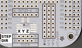
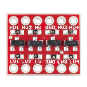
BBB voltage boost
Need to convert from 3.3V to 5V per above spec
BBB breakout: https://www.adafruit.com/products/572]]
Logic level converter: https://www.sparkfun.com/products/12009]]
2015-09-10
Successfully tested BBB voltage boost X channel on standalone motor
Tested OEM650 drives and discovered only 2/4 are functional. Unclear if I broke these last time I used them or they were always broken. Discarded defective drives
Current strategy: use MDrive23 for X1, Y1. Use original motors with OEM650 for X2, Y2. Z1 will not be hooked up at this time but will still be accessible on connector if required. Only X1 and Y1 will be used in initial testing since stock BBB configuration only supports 3 axes
Working on polishing earlier tables to verify its safe to rewire X1, Y1 for completely different purpose signals. I'll then have to cut wires and solder in the MDrive23's.
X1, Y1 motor rewire
| P2 pin | Orig color | New color | Function |
|---|---|---|---|
| 1 | Green | White | Opto |
| 2 | White | Orange | Step clock |
| 3 | White-red | Blue | Direction |
| 4 | Black | Brown | Enable |
| 5 | Red | Black | GND |
| 6 | White-green | Red | V+ |
50 pin table updated with this in mind
2015-09-13
Both X1 and Y1 MDrive23 motors have been integrated and tested
Made a second BBB 5V cape and tested X and Y successfully. Z pinout non-intuitive and made bad assumption. Need to make a more custom config and/or review CRAMPS config
CRAMPS pinout
P8
| Pin | CPU GPIO | CNC function | I/O | Note |
|---|---|---|---|---|
| 07 | gpio2[2] | X max | I | |
| 08 | gpio2[3] | X min | I | |
| 09 | gpio2[5] | Y max | I | |
| 10 | gpio2[4] | Y min | I | |
| 11 | gpio1[13] | FET 1 : heated bed | ||
| 12 | gpio1[12] | X dir | O | |
| 13 | gpio0[23] | X step | O | |
| 14 | gpio0[26] | Y dir | O | |
| 15 | gpio1[15] | Y step | O | |
| 16 | gpio1[14] | eMMC Enable | O | |
| 17 | gpio0[27] | estop | I | |
| 18 | gpio2[1] | Z dir | O | |
| 19 | gpio0[22] | Z step | O | |
| 26 | gpio1[29] | estop out |
P9
| Pin | CPU GPIO | CNC function | I/O | Note |
|---|---|---|---|---|
| 11 | Z max | |||
| 12 | E0 dir | |||
| 13 | Z min | |||
| 14 | Axis enable | |||
| 15 | FET 2 | |||
| 16 | E0 step | |||
| 17 | E1 step | |||
| 18 | E1 dir | |||
| 21 | FET 4 | |||
| 22 | FET 6 | |||
| 23 | Machine power | |||
| 24 | E2 step | |||
| 25 | LED | |||
| 26 | E2 dir | |||
| 27 | FET 3 |
Seems relatively complete with the notable issue that only XYZ have limit switches (E0/E1 do not). Probably not worth it to diverge from this where not needed. E0 and E1 will become X2 and Y2. TODO: figure out where limit switches should go
Limit switches
Confirm that limit switches take 5V. Is there a part or something I can read to confirm this?
Test them
Boards have a single part:
IUGN
3140U
230
- 4.5 - 24V
- 20 mA max open collector
Successfully fired laser!
2015-09-14
Step calibration
1000 steps = 0.001" 1,000,000 steps per inch…
20 TPI, assume 200 step steppers 4,000 real steps per inch 250 microstepping?
- 250 * 200 = 50,000 steps per rev
- This is a legal stepping value
What is the fastest step rate the BBB can generate? Is this going to be problematic?
BBB stepgen limits
latency-test by itself will just report soft stepping. How can I measure the PRUs?
Figure 6.1 Step /direction signal timing……………………………………………6-3
- Step high: >= 100 ns
- Step low: >= 100 ns
- Dir: 50 ns setup time to step rise
- Dir: 100 ns hold time to step (must be held during entire step?)
http://linuxcnc.org/docs/html/man/man9/stepgen.9.html]]
- stepgen.N.steplen u32 rw: The length of the step pulses, in nanoseconds. Measured from rising edge to falling edge.
- stepgen.N.stepspace u32 rw (step types 0 and 1 only) The minimum space between step pulses, in nanoseconds. Measured from falling edge to rising edge. The actual time depends on the step rate and can be much longer. If stepspace is 0, then step can be asserted every period. This can be used in conjunction with hal_parport’s auto-resetting pins to output one step pulse per period. In this mode, steplen must be set for one period or less
Calibration test: https://www.youtube.com/watch?v=6010s7QhAiw]]
Laser ablation tests
| Material | Wavelength | Power | Objective | Result | Notes |
| Anodized Al (black) | 532 | Max | Mit20x | No noticible result unntil ~8 shots | |
| Anodized Al (black) | 532 | Max | MitNUV50x | First shot |
2015-09-17
Yesterday's cnc_microscope tests significantly increased BBB step rates (possibly to unreliability). Use those results to make a reasonable speed first cut at brainscope XY configuration
Do I need to order a power supply or can I use the Compumotor 75V supply for both the OEM650 and the MDrive 23?
- The MDrive 23 accepts a broad input voltage range from +12 to +75 VDC
- Conclusion: use the 75V supply for both
- 5V will be generated from BBB
About 300 mA per MDrive23 when moving
X axis not moving…what happened?
- Most likely cause appears to be poor X1 ground wire between 50 pin ribbon cable and breakout board
- Connector is a bit stressed…should I try to get another breakout board? Cost?
X and Y axis are now moving
X axis tests:
- Cannot move very far left off center…not nearly the leadscrew length. Why?
- When I move to crash position on right it cannot by itself get moving again
- Right now I can cheat by reaching under and moving it slightly to unstick it
- This may be a good reason to up priority on supporting the limit switches
- Should be sufficient for an initial laser bitmap
Next objective: get laser under Python control
- Good place to start: [1]
Open issues:
- Fine focus knob still falling off. Need to figure out how to torque it better, using locktite if necessary
- Laser aperature alignment poor at 50x: only cuts lower left half of unmaked area. Perfect at 20x
- Monitor 50 pin ribbon cable reliability
2018-06-05
motor
M061-LS02
[2]
type: LEADS
typical step time: 2.5 ms
nominal volts: 5 V
bipolar series
A per winding: 0.7 A
H per winding: 38.3 mH
Hold torque: 60
Rorze RD-021M8 resistor value
Ir = 0.7 A
Full step:
I = Ir = 0.7 A
Microstep:
I = 1.414 * Ir
1.414 * 0.7 = 0.9898 = 1.0 A
X ={I/(0.1108×Ir+0.66)}
0.7 / (0.1108* 0.7 + 0.66) = 0.949075329  = 0.95
1.0 / (0.1108* 1.0 + 0.66) = 1.3
R = 8.2×X/(8.2-X)
8.2 * 0.95 / (8.2 - 0.95) = 1.074482759 = 1.1
8.2 * 1.3 / (8.2 - 1.3) = 1.5
2018-06-27
Effort to overhaul control system, especially for upper XY
Rorze RD-021M8 resistor value: 1.5 ohm?
