Difference between revisions of "User:Mcmaster/cnc microscope"
| Line 1: | Line 1: | ||
| − | |||
| − | |||
First section is about what the system does as of today. Below that shows how it arrived there | First section is about what the system does as of today. Below that shows how it arrived there | ||
| Line 47: | Line 45: | ||
== 0.0 == | == 0.0 == | ||
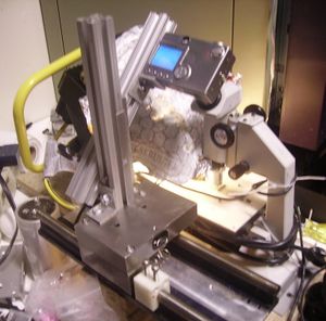
| − | + | [[File:mcmaster_cnc_microscope_mk0_overview.jpg|300 px]] | |
Above: manually operated system. Clicked point and shoot camera to take pictures. t-slot aluminum lines it up to the monocle. | Above: manually operated system. Clicked point and shoot camera to take pictures. t-slot aluminum lines it up to the monocle. | ||
| Line 53: | Line 51: | ||
== 0.1 == | == 0.1 == | ||
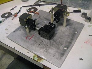
| − | + | [[File:mcmaster_cnc_microscope_mk0_linear_stage_springy_planning.jpg|300 px]] | |
Above: stepper motors with (to be added) springs to couple them to the linear stages. IIRC it took way too much force to turn the stags leading the springs to turn the stages in unpredictable bursts. | Above: stepper motors with (to be added) springs to couple them to the linear stages. IIRC it took way too much force to turn the stags leading the springs to turn the stages in unpredictable bursts. | ||
| Line 59: | Line 57: | ||
== 0.2 == | == 0.2 == | ||
| − | + | [[File:mcmaster_cnc_microscope_mk0_stage_almost_there_perspective.jpg|300 px]] | |
Above: Instead tried to spring load some gears onto the stages. Slightly non-linear but very predictable. I don't recall what the specific problem was with this system, but probably just difficult to keep the gears aligned | Above: Instead tried to spring load some gears onto the stages. Slightly non-linear but very predictable. I don't recall what the specific problem was with this system, but probably just difficult to keep the gears aligned | ||
| Line 69: | Line 67: | ||
== 1.0 == | == 1.0 == | ||
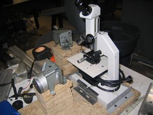
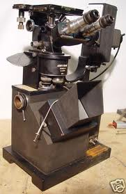
| − | + | [[File:mcmaster_cnc_microscope_mk1_a_unitron_n.png|200 px]] | |
Above: an unmodified microscope of the same model | Above: an unmodified microscope of the same model | ||
| Line 75: | Line 73: | ||
== 1.1 == | == 1.1 == | ||
| − | + | [[File:mcmaster_cnc_microscope_mk1_overview2.jpg|300 px]] | |
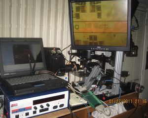
Above: basic idea of setup. Microscope stage has been removed and the microscope has been turned upside down to make it right side up. Point and shoot similar to mk0. I soldered wires onto the shutter controllers and routed them to EMC2 (LinuxCNC) software that ran g-code to move Sherline 2000 mill stages (something I already had…and the only "nice" thing I had at the time). Pictures were snapped by sending coolant mist (focus), coolant flood (snap picture), followed by coolant off (release shutter). $20 laptop with a wireless card from a scrapped access point. | Above: basic idea of setup. Microscope stage has been removed and the microscope has been turned upside down to make it right side up. Point and shoot similar to mk0. I soldered wires onto the shutter controllers and routed them to EMC2 (LinuxCNC) software that ran g-code to move Sherline 2000 mill stages (something I already had…and the only "nice" thing I had at the time). Pictures were snapped by sending coolant mist (focus), coolant flood (snap picture), followed by coolant off (release shutter). $20 laptop with a wireless card from a scrapped access point. | ||
| − | + | [[File:mcmaster_cnc_microscope_mk1_z_axis.jpg|200 px]] | |
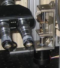
Above: since the original stage had been removed I needed a way to focus it. Linear stage removed from a broken spectrometer found in school dumpster and spring loaded with a rubber band to maintain position (intended to be gravity spring loaded but I'm holding it the "wrong" way) | Above: since the original stage had been removed I needed a way to focus it. Linear stage removed from a broken spectrometer found in school dumpster and spring loaded with a rubber band to maintain position (intended to be gravity spring loaded but I'm holding it the "wrong" way) | ||
| Line 91: | Line 89: | ||
== 2.1 == | == 2.1 == | ||
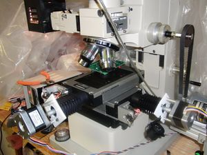
| − | + | [[File:mcmaster_cnc_microscope_mk2_stage.jpg|300 px]] | |
Above: very first test before installing the tip tilt. Note riser block is still present below stage. This takes a way a lot of my clearance making it so that I couldn't use Mitutoyo objectives | Above: very first test before installing the tip tilt. Note riser block is still present below stage. This takes a way a lot of my clearance making it so that I couldn't use Mitutoyo objectives | ||
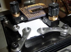
| − | + | [[File:mcmaster_cnc_microscope_mk2_tip_tilt.jpg|300 px]] | |
Above: tip tilt installed shortly thereafter. | Above: tip tilt installed shortly thereafter. | ||
| Line 107: | Line 105: | ||
== 2.2 == | == 2.2 == | ||
| − | + | [[File:mcmaster_cnc_microscope_mk2_picomotor_prototype.jpg|200 px]] | |
Added picomotor theta X/Y. have drivers and stage setup for Z but never installed picomotor mostly becasue I never replaced the cable | Added picomotor theta X/Y. have drivers and stage setup for Z but never installed picomotor mostly becasue I never replaced the cable | ||
| Line 117: | Line 115: | ||
Got new motors: 17PM-K318-04V | Got new motors: 17PM-K318-04V | ||
| − | + | * 17PM-K: [http://www.eminebea.com/en/product/rotary/steppingmotor/hybrid/standard/17pm-k.shtml] | |
| − | + | ** Datasheet: [http://www.eminebea.com/en/product/rotary/steppingmotor/hybrid/standard/data/17pm-k.pdf] | |
| − | + | * General motor guide: [http://www.nmbtc.com/pm-step-motors/engineering/pdf/pm_select.pdf] | |
Tried OEM650 drivers but burned out a motor and ultimately went back to old drivers | Tried OEM650 drivers but burned out a motor and ultimately went back to old drivers | ||
| Line 125: | Line 123: | ||
New motors: TYPE 17PM-K318-04V | New motors: TYPE 17PM-K318-04V | ||
| − | + | * Yellow A-1 | |
| − | + | * Black: A-C | |
| − | + | * Red A-2 | |
| − | + | * Blue B-1 | |
| − | + | * White B-C | |
| − | + | * Orange B-2 | |
Driver settings (PMC VS series): | Driver settings (PMC VS series): | ||
| Line 163: | Line 161: | ||
== 2.4 == | == 2.4 == | ||
| − | + | [[File:mcmaster_cnc_microscope_mk2_3.jpg|300 px]] | |
As of 11/09/2013 | As of 11/09/2013 | ||
| Line 169: | Line 167: | ||
Recent changes: | Recent changes: | ||
| − | + | * Use of hardware DIY indexer has enabled microstepping. Significant noise/vibration reduction | |
| − | + | ** [[mcmaster:pr0ndexer_protocol|proposed protocol]] | |
| − | + | * Implemented acceleration/decceleration logic in hardware indexer | |
| − | + | * On UPS (I haven't had a problem, but its right next to my room UPS) | |
Y motor drive box may be beginning to see mechanical failure but move to microstepping and hardware indexer has smoothed acceleration profiles significantly which seems to have sufficiently mitigated suspected stripped gear for the time being | Y motor drive box may be beginning to see mechanical failure but move to microstepping and hardware indexer has smoothed acceleration profiles significantly which seems to have sufficiently mitigated suspected stripped gear for the time being | ||
| Line 180: | Line 178: | ||
Revisions: | Revisions: | ||
| − | + | * pr0ntools: 1dea224a62bef5f0a02e2c41e81d85553db30ab0, Sat Nov 9 20:21:30 2013 -0800 | |
| − | + | * uvcada: c550026a99c50a63e70f278c2e98e98d6e0486ef, Sat Nov 9 19:51:01 2013 -0800 | |
| − | + | * python: 2.7 | |
=== Indexer === | === Indexer === | ||
| Line 188: | Line 186: | ||
Revisions: | Revisions: | ||
| − | + | * pr0ndexer 010652d4ddc8f06d54ff01062372cb9ba916f12e, Sat Nov 9 19:50:36 2013 -0800 | |
| − | + | * Toolchain: arm-none-eabi-gcc (GNU Tools for ARM Embedded Processors) 4.7.4 20130913 (release) [ARM/embedded-4_7-branch revision 202601] | |
| − | + | * STM32 eval borad. CPU rev L1 | |
=== Driver === | === Driver === | ||
| Line 196: | Line 194: | ||
Drivers (2): Precision Motion Controls PMC VS series | Drivers (2): Precision Motion Controls PMC VS series | ||
| − | + | * [[File:pmc_vsbro1.pdf|Product brief]] | |
| − | + | * [[File:pmc_vsmanual.pdf|Manual]] | |
Switches | Switches | ||
| Line 224: | Line 222: | ||
Switch/current: off means add current | Switch/current: off means add current | ||
| − | + | * S2-3: 0.095 A | |
| − | + | * S2-4: 0.19 A | |
| − | + | * S2-5: 0.38 A | |
| − | + | * S2-6: 0.76 A | |
| − | + | * S2-7: 1.52 A | |
| − | + | * S2-8: 3.04 A | |
Microstepping: | Microstepping: | ||
| Line 266: | Line 264: | ||
Wires: | Wires: | ||
| − | + | * red: 5V @ 500mA direct from USB port | |
| − | + | * black: ground | |
| − | + | * white: 3.3V RX into USB port | |
| − | + | * green: 3.3V TX out of the USB port | |
== 2.5 == | == 2.5 == | ||
| − | + | [[File:mcmaster_cnc_microscope_mk2_4.jpg|300 px]] | |
07/19/2014: is currently out of service due to broken laptop (and has been for a while). replacement parts in the mail. cleaning up electronics while its down | 07/19/2014: is currently out of service due to broken laptop (and has been for a while). replacement parts in the mail. cleaning up electronics while its down | ||
| Line 283: | Line 281: | ||
want to add: | want to add: | ||
| − | + | * finish rewiring electronics. either make pcb or use phoenix contact DIN mount screw terminals | |
| − | + | * get a cabinet to store spare carasols loaded with objectives | |
| − | + | * Can fit the confocal microscope next to it now that I have more room on the desk? | |
| − | + | * would be nice to get a real anti-vibration table | |
| − | + | * consider adding continuous running hepa filter at top (make it like laminar flow workstation) | |
| − | + | ** problems blowing dies away? | |
== 2.6 == | == 2.6 == | ||
| − | + | [[File:mcmaster_cnc_microscope_mk6_bbb.jpg|300 px]] | |
Controller replaced with BBB | Controller replaced with BBB | ||
| Line 306: | Line 304: | ||
"g0 x5120" 5 mm | "g0 x5120" 5 mm | ||
| − | + | * 1000 steps / unit | |
| − | + | * 51200 steps / rev | |
| − | + | * 100 rev => 5 mm | |
| − | + | * 1 rev => 50 um | |
| − | + | * 1 real motor step => 250 nm | |
| − | + | * 1 microstep => ~ 1 nm | |
Appears to be either missing steps or I have the ratios wrong. Consider setting up a repeatbility test using microscope itself to target something. | Appears to be either missing steps or I have the ratios wrong. Consider setting up a repeatbility test using microscope itself to target something. | ||
| Line 322: | Line 320: | ||
Original connectors: | Original connectors: | ||
| − | + | * P1: DB25 controller interface | |
| − | + | * P2: limit switch? | |
| − | + | * P3: limit switch? | |
| − | + | * P4: motor encoder | |
| − | + | * P5: motor main (motor P1) | |
| − | + | * P6: motor power (removed) | |
== P1: controller interface == | == P1: controller interface == | ||
| Line 388: | Line 386: | ||
NOTE: original cables had these two ports which were repurposed into power lines: | NOTE: original cables had these two ports which were repurposed into power lines: | ||
| − | + | * P2 | |
| − | + | * P3 | |
Probably intended to be used for limit switches | Probably intended to be used for limit switches | ||
| Line 499: | Line 497: | ||
7/16" socket to remove fine/medium knobs (remove circular cover first) | 7/16" socket to remove fine/medium knobs (remove circular cover first) | ||
| − | + | * left side comes off, right side doesn't | |
| − | + | * remove by holding left fine focus in place and turning | |
Revision as of 02:21, 5 March 2019
First section is about what the system does as of today. Below that shows how it arrived there
"pr0nscope"
Current configuration
Driver controller: New Focus ethernet controller
Joystick: New Focus MODEL 8754 PICOMOTOR JOYSTICK
XY stage
Klinger/Micro-Controle/Newport variable reluctance UT100-50PP (50 mm). I've read these are rated to 0.1 um accuracy. IIRC they use UE30PP motor but you can get a stepper version.
However, instead of using the variable reluctance motor a stepper motor was attached via a custom machined adapter plate, flexible shaft coupler, and 4-40 standoffs from discarded computers
Optics
Olympus BH2-UMA illuminator
Olympus LH50A lamphouse
Think Nikon makes the lamp power supply
Misc Mitutoyo Plan Apo, a couple Olympus NeoSPlan DIC
NeoSPlan DIC prism set
Sensitive tint plate
Polarizer, analyzer
AmScope MD800E camera (using Linux GSPCA driver I wrote)
Misc
CD4069 to convert 3.3V indexer logic level to 5V stepper drive logic level
Unknown who makes the base but its very heavy duty
mk0
Failed attempts that never made a working system
0.0
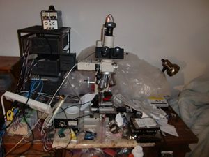
Above: manually operated system. Clicked point and shoot camera to take pictures. t-slot aluminum lines it up to the monocle.
0.1
Above: stepper motors with (to be added) springs to couple them to the linear stages. IIRC it took way too much force to turn the stags leading the springs to turn the stages in unpredictable bursts.
0.2
Above: Instead tried to spring load some gears onto the stages. Slightly non-linear but very predictable. I don't recall what the specific problem was with this system, but probably just difficult to keep the gears aligned
mk1
Purchased a Unitron inverted metallurgical microscope because it was the least expensive metallurgical microscope I could buy ($200 shipped IIRC).
1.0
Above: an unmodified microscope of the same model
1.1
Above: basic idea of setup. Microscope stage has been removed and the microscope has been turned upside down to make it right side up. Point and shoot similar to mk0. I soldered wires onto the shutter controllers and routed them to EMC2 (LinuxCNC) software that ran g-code to move Sherline 2000 mill stages (something I already had…and the only "nice" thing I had at the time). Pictures were snapped by sending coolant mist (focus), coolant flood (snap picture), followed by coolant off (release shutter). $20 laptop with a wireless card from a scrapped access point.
Above: since the original stage had been removed I needed a way to focus it. Linear stage removed from a broken spectrometer found in school dumpster and spring loaded with a rubber band to maintain position (intended to be gravity spring loaded but I'm holding it the "wrong" way)
mk2
2.0
Original microscope without computer control
2.1
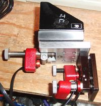
Above: very first test before installing the tip tilt. Note riser block is still present below stage. This takes a way a lot of my clearance making it so that I couldn't use Mitutoyo objectives
Above: tip tilt installed shortly thereafter.
Used motors, mixed types. Minebea size 17 frames
PMC VS series drivers that I found in the trash
"USBIO DAQ" board used to bit bang step/direction signals
2.2
Added picomotor theta X/Y. have drivers and stage setup for Z but never installed picomotor mostly becasue I never replaced the cable
Ultimately it turned out I didn't really need the picomotors. The real issue was that the original leadscrew was poor quality. I just use them as leadscrews and don't use the motorized capabilities. At first I had problems bumping stage and so used the joystick to avoid touching things but now I'm quicker just adjusting by hand without issue.
2.3
Got new motors: 17PM-K318-04V
Tried OEM650 drivers but burned out a motor and ultimately went back to old drivers
New motors: TYPE 17PM-K318-04V
- Yellow A-1
- Black: A-C
- Red A-2
- Blue B-1
- White B-C
- Orange B-2
Driver settings (PMC VS series):
Motor current
S2-3:S2-8: 001111
0.95 + 0.19A
switch off selects it
Seems to be stalling...upgrade to 0.38A
   1
       1 1
       2 1
       3 1
       4 1
       5 1
       6 1
       7 0
       8 1
   2
       1 1
       2 1
       3 1
       4 1
       5 0
       6 1
       7 1
       8 1
2.4
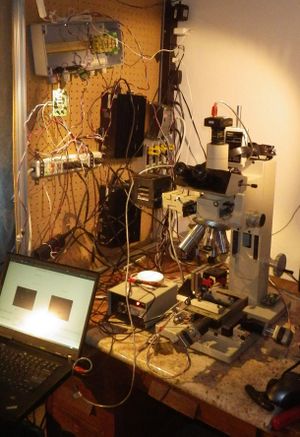
As of 11/09/2013
Recent changes:
- Use of hardware DIY indexer has enabled microstepping. Significant noise/vibration reduction
- Implemented acceleration/decceleration logic in hardware indexer
- On UPS (I haven't had a problem, but its right next to my room UPS)
Y motor drive box may be beginning to see mechanical failure but move to microstepping and hardware indexer has smoothed acceleration profiles significantly which seems to have sufficiently mitigated suspected stripped gear for the time being
Control software
Revisions:
- pr0ntools: 1dea224a62bef5f0a02e2c41e81d85553db30ab0, Sat Nov 9 20:21:30 2013 -0800
- uvcada: c550026a99c50a63e70f278c2e98e98d6e0486ef, Sat Nov 9 19:51:01 2013 -0800
- python: 2.7
Indexer
Revisions:
- pr0ndexer 010652d4ddc8f06d54ff01062372cb9ba916f12e, Sat Nov 9 19:50:36 2013 -0800
- Toolchain: arm-none-eabi-gcc (GNU Tools for ARM Embedded Processors) 4.7.4 20130913 (release) [ARM/embedded-4_7-branch revision 202601]
- STM32 eval borad. CPU rev L1
Driver
Drivers (2): Precision Motion Controls PMC VS series
Switches
 1
     1 0
     2 1
     3 0
     4 1
     5 1
     6 1
     7 0
     8 1
 2
     1 1
     2 1
     3 1
     4 1
     5 0
     6 1
     7 1
     8 1
Switch/current: off means add current
- S2-3: 0.095 A
- S2-4: 0.19 A
- S2-5: 0.38 A
- S2-6: 0.76 A
- S2-7: 1.52 A
- S2-8: 3.04 A
Microstepping:
| Level | S1-1 | S1-2 | |
|---|---|---|---|
| 50000 | OFF | OFF | OFF |
| 25000 | ON | OFF | OFF |
| *10000 | OFF | ON | OFF |
| 2000 | ON | ON | OFF |
| 51200 | OFF | OFF | ON |
| 25600 | ON | OFF | ON |
| 6400 | OFF | ON | ON |
| 400 (none?) | ON | ON | ON |
Theta control
Mirror mount: Newport P100-P2
Motors: Picomotor, model ???
Drivers (2): New Focus something
Adafruit serial adapter
Wires:
- red: 5V @ 500mA direct from USB port
- black: ground
- white: 3.3V RX into USB port
- green: 3.3V TX out of the USB port
2.5
07/19/2014: is currently out of service due to broken laptop (and has been for a while). replacement parts in the mail. cleaning up electronics while its down
07/28/2014: back online! Down for a few months but rolling once more
built t-slot cage around desk. mounted pegboard to which I attached the various electronics to clean them up and get them off the desk (the idea cabinet thing just wasn't working very well)
want to add:
- finish rewiring electronics. either make pcb or use phoenix contact DIN mount screw terminals
- get a cabinet to store spare carasols loaded with objectives
- Can fit the confocal microscope next to it now that I have more room on the desk?
- would be nice to get a real anti-vibration table
- consider adding continuous running hepa filter at top (make it like laminar flow workstation)
- problems blowing dies away?
2.6
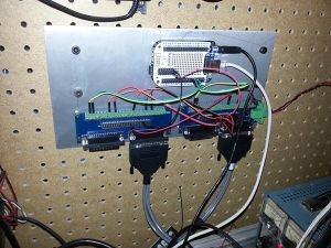
Controller replaced with BBB
Motors replaced with IMS NEMA 17 integrated drivers
Circa 2015-09-15
Discovered my MDrive17 units are set to 51200 microstepping. This is a bit high...may pose issues getting BBB to step fast enough especially given already high gear ratio
Created high performance BBB configuration. Although my step rate is way smoother and higher than pr0ndexer, the high microstepping meant that I stayed at about the same max velocity (possibly losing some). About 4 rev/s max
"g0 x5120" 5 mm
- 1000 steps / unit
- 51200 steps / rev
- 100 rev => 5 mm
- 1 rev => 50 um
- 1 real motor step => 250 nm
- 1 microstep => ~ 1 nm
Appears to be either missing steps or I have the ratios wrong. Consider setting up a repeatbility test using microscope itself to target something.
2015-08-29
NEMA 17 motor pinout
Original connectors:
- P1: DB25 controller interface
- P2: limit switch?
- P3: limit switch?
- P4: motor encoder
- P5: motor main (motor P1)
- P6: motor power (removed)
P1: controller interface
DB25 Pin |
To |
Wire color | Function | |
|---|---|---|---|---|
| 1 | P4.1 | Red | ||
| 2 | P4.6 | Green | ||
| 3 | P4.8 | White | ||
| 4 | ||||
| 5 | Old: P2.5 New: P5.1 |
Black | Old: lim sw New: ground |
|
| 6 | ||||
| 7 | P3.2 New: P5.1 |
Black | Old: lim sw New: ground |
|
| 8 | ||||
| 9 | ||||
| 10 | ||||
| 11 | P5.3 | Red | OPTO | 5V Orange BBB P9.5-6 |
| 12 | P5.5 | Black | EN | N/C |
| 13 | ||||
| 14 | P4.5 | Brown | ||
| 15 | P4.7 | Blue | ||
| 16 | P4.4 | Black | ||
| 17 | P2.1 New: P5.2 |
White | Old: limit sw New: +V |
|
| 18 | Old: P2.3 New: N/C |
Black | Old: shield New: N/C |
|
| 19 | Old: P3.1 New: P5.2 |
White | Old: limit sw New: +V |
|
| 20 | Old: P3.3 New: N/C |
Black | Old: shield New: N/C |
|
| 21 | ||||
| 22 | ||||
| 23 | ||||
| 24 | P5.4 | Green | SCLK ("step") |
X: BBB P8.13 Y: BBB P8.15 Blue |
| 25 | P5.6 | White | DIR | X: BBB P8.12 Y: BBB P8.14 White |
NOTE: original cables had these two ports which were repurposed into power lines:
- P2
- P3
Probably intended to be used for limit switches
P2/P3: limit switches
P2 (original wiring):
P2 Pin |
DB25 pin |
Wire color | Function | |
|---|---|---|---|---|
| 1 | 17 | White | ||
| 2 | 5 | Black | ||
| 3 | 18 | Black | Shield | N/C as power |
P3 (original wiring):
P3 Pin |
DB25 pin |
Wire color | Function | |
|---|---|---|---|---|
| 1 | 19 | White | ||
| 2 | 7 | Black | ||
| 3 | 20 | Black | Shield | N/C as power |
P4: encoder
Mot P1 |
P1 | Wire color | Function | |
|---|---|---|---|---|
| 1 | 1 | Red | ||
| 2 | N/C | N/C | ||
| 3 | N/C | N/C | ||
| 4 | 16 | Black | ||
| 5 | 14 | Brown | ||
| 6 | 2 | Green | ||
| 7 | 15 | Blue | ||
| 8 | 3 | White | ||
| 9 | N/C | N/C | ||
| 10 | N/C | N/C |
P5: motor main
2.4.3 Motor P1 - Power, communications and logic (universal inputs)
Mot P1 |
P1 | Wire color | Function | |
|---|---|---|---|---|
| 1 | 5 7 |
Black | Ground | |
| 2 | 17 19 |
Red | V+ | |
| 3 | 11 | Red | OPTO | |
| 4 | 24 | Green | SCLK | |
| 5 | 12 |
Black | EN | |
| 6 | 25 | White | DIR | |
| 7 | N/C | N/C | +5V | |
| 8 | N/C | N/C | CLK | |
| 9 | N/C | N/C | CGND | |
| 10 | N/C | N/C | MOSI | |
| 11 | N/C | N/C | CS | |
| 12 | N/C | N/C | MISO |
P6: power
Removed. Never pinned out but was just red + black wire
Misc notes
T7 star to take off BH2-UMA
7/64" allen to remove nosepiece adapter from Z assembly
5/32" allen to remove fine/medium focusing assembly from Z assembly
3/16" allen to remove fine/medium backplate to expose gears
7/16" socket to remove fine/medium knobs (remove circular cover first)
- left side comes off, right side doesn't
- remove by holding left fine focus in place and turning
