FEI FIB 200
This seems to be a pretty popular FIB. Based on the XL30?
Contents
Refilling
Videos for GIS refill: https://www.youtube.com/channel/UCebcTTg_Al48R9Uxdy8sS9Q
Chemicals Markus is using to refill (TODO: get image of Ga bottle, process):


Calibration
General procedure is to wobble the focus and minimize how much drift occurs when sweeping. Looks something like this: https://youtu.be/Ln2GDMw-Vf8
Startup
- Turn on roughing vacuum pump (sometimes the automated switching has failed, if not the computer does this for you)
- In the FEI control software, click Pump
- This will startup the TMP (Turbo Molecular Pump)
- After chamber vacuum is around 10^-6, the status should say Vac OK
- Press the HT (High Tension) physical switch on the desk
- Click the HV icon in the software (it will show an error if you haven't pressed the physical switch first)
- Wait for the voltage to ramp up to 30kV (unless in the beam current drop-down menu, you've selected low-magnification 10kV)
- You might hope the computer auto-emission current algorithm works, if not...
- Click apply near the emission current set-point textbox which shows 2.2
- This should disable the feature, changing the icon from yellow to grey
- Slowly (there is lag between clicking and seeing anything change) increase the extractor voltage from it's default of 12.00kV
- Clicking in the whitespace will increase by 10X MORE than clicking the arrow buttons
- Click apply above the extractor setting, to set/apply the default of 12.00kV
- If this is causing the emission current to crash back to 0pA, then you can slowly click back down until the emission is around 2.2 pA
- if you max out the extractor, and still see no emission current, then start increasing the suppressor voltage
- if you see the emission current jump to it's max of 13pA, quickly click "apply" on the extractor to reset it to 12.00kV
- Click apply near the emission current set-point textbox which shows 2.2
- once the emission current is stable around 2pA or so, and the extractor is set to 12.00kV, you're good to move on and attempt imaging
Focusing
On photoresist which is totally planar
Since a sample (wafer, etc) that's been evenly spincoated with photoresist will not have any distinct features to focus on, one way to get started is as follows:
- draw a hollow box pattern
- mill the pattern for 5 to 10 seconds
- erase the pattern (click the eraser several times, as sometimes patterns get stuck in memory)
- set live imaging mode to low or medium res
- get your hands ready to act quick on the coarse focus and astigmatism knobs!
- start live imaging!
- quickly adjust the focus in attempt to visualize and sharpen the box you just milled
- if you ablate away the box before focusing well, mill another box, erase the pattern, and perform focusing again
- zoom in 2 to 5 times past the working magnification you desire
- mill a box, erase the pattern, focus again
- now you can zoom back out and get to lithography!
NOTE: you need to re-perform this anytime you adjust the AVA (Automatic Variable Aperture), aka change the beam current
Markus
mcmaster: took a bunch of notes, but they were lost. I still have the pictures though
Problems when acquired:
- LMIS empty
- Fabricated replacement using Ga from Sigma-Aldrich, tungsten wire, syringe, and DIY spot welder
- Sources were refilled?
- Detector tube bad (outgassed)
- Replaced
- XeF2 leak. Damaged stage gears
- Removed XeF2 GIS and blanked off
- Bought similar replacement gears, machined to fit
- TOOD: install new seals. Requires special XeF2 rated version not in other GIS
- Faulty power supply
- Repaired module (replaced resistor?)
- Bad seal on pneumatic stabilizer
- Bought (silicone?) sheet to repair
- Turbo pump sometimes noisy, but seems to still work
Special modification to keep under vacuum when not in use. Time delay relay to make pulling vacuum in chamber softer (keep air inlet open initially to create a weak vacuum, then close it to create a hard vacuum):

GIS
GIS cluster:


A new Pt injector tip:


This XeF2 injector sat for a long time in storage. The XeF2 ate through the seals and caused considerable damage in the FIB


Computer


Misc
Aperture motor test: https://youtu.be/TIqlTjR2UH4
Test edit after calibration (cut trace):


GIS controller (pneumatics + heater controllers)

High voltage power supply


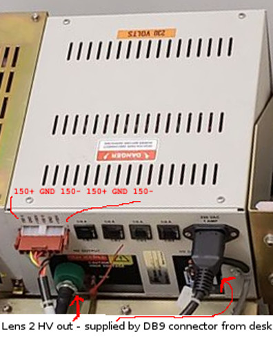 This box contains deflection amp power supply, as well as the HV supply for lens 2 (which is not powered from 230VAC, rather from a lower-voltage DB-9 type connector attached to the back of the desk). Deflection amp is provided with an output of: (150VDC+ GND 150VDC- 150VDC+ GND 150VDC-) Lens2 HV output is (???)


Main power distribution


Chamber camera on left screen

Doc describing the LMIS column

CDEM
Continuous Dynode Electron Multiplier (CDEM)


Misc


