Difference between revisions of "Allied MultiPrep"
(Tag: Visual edit) |
(Tag: Visual edit) |
||
| (11 intermediate revisions by the same user not shown) | |||
| Line 1: | Line 1: | ||
| − | <br /> | + | Key links |
| + | |||
| + | *Calibration: <nowiki>https://www.youtube.com/watch?v=Ul2JN875x3U</nowiki> | ||
| + | *Parallel lapping: http://jiam.utk.edu/PDF/Allied-Parallel-Lapping-Integrated-Circuits.pdf | ||
| + | **225 RPM CCW | ||
| + | **Rotation: full (speed 8) | ||
| + | **Oscillation 3<br /> | ||
==Motor== | ==Motor== | ||
| − | Both motors (drive, osc) | + | Both motors (drive, osc) are identical |
| + | |||
| + | Healthy readings TLDR | ||
| + | |||
| + | *6 ohm nominal | ||
| + | **Higher indicates carbon dust, possibly much higher (eddy currents I guess) | ||
| + | *Vmax | ||
| + | **Motor: 19.1 V | ||
| + | **Osc: 7.6 V | ||
| + | **Drive: 15.0 V | ||
| + | *No load test | ||
| + | **Healthy around | ||
| + | ***12.21 V @ 153 mA | ||
| + | ***12.21 V @ 180 mA | ||
| + | **Old motors: 12.22V @ 1.25 A | ||
| + | |||
| + | <br /> | ||
PITTMAN | PITTMAN | ||
| Line 43: | Line 65: | ||
What is max voltage allied puts out on motors? | What is max voltage allied puts out on motors? | ||
| − | * | + | *4-8 |
**7.6 (fixed) | **7.6 (fixed) | ||
**osc | **osc | ||
| − | * | + | *3-7 |
**15.0 (max) | **15.0 (max) | ||
**drive | **drive | ||
| Line 53: | Line 75: | ||
<br /> | <br /> | ||
==Head connector== | ==Head connector== | ||
| + | |||
| + | Official cable uses 24 AWG (Carol C0603) | ||
| Line 60: | Line 84: | ||
*3 mm pitch | *3 mm pitch | ||
*Head female, cable male | *Head female, cable male | ||
| − | * | + | *Molex Microfit 3 |
| − | **<nowiki>https://www.digikey.com/product-detail/en/amphenol-icc-fci/10132445-08LF/609-5283-ND/7590945</nowiki> | + | **aka Amphenol Minitek Pwr™ 3.0 Series |
| + | ***<nowiki>https://www.digikey.com/product-detail/en/amphenol-icc-fci/10132445-08LF/609-5283-ND/7590945</nowiki> | ||
| + | |||
| + | <br /> | ||
| + | [[File:Molex microfit3 4x2f.png|none|thumb|Molex 8-CKT female(PS-43045.pdf pg 10, 8.4 STANDARD POLARIZATION FOR RECEPTACLES)]] | ||
| − | |||
| − | [[File:Mcmaster allied multiprep head cable standard.jpg|none|thumb]] | + | {| class="wikitable" |
| + | !Microfit 4x2 | ||
| + | !Signal | ||
| + | !Breakout cable color | ||
| + | !Notes | ||
| + | |- | ||
| + | |1 | ||
| + | |Hall | ||
| + | |Black | ||
| + | | | ||
| + | |- | ||
| + | |2 | ||
| + | |Hall w/ cap | ||
| + | |Red | ||
| + | | | ||
| + | |- | ||
| + | |3 | ||
| + | |Drive | ||
| + | |Orange | ||
| + | | | ||
| + | |- | ||
| + | |4 | ||
| + | |Osc | ||
| + | |Yellow | ||
| + | | | ||
| + | |- | ||
| + | |5 | ||
| + | |Chassis ground | ||
| + | |Green | ||
| + | |N/C on main cable | ||
| + | |- | ||
| + | |6 | ||
| + | |Hall w/ cap | ||
| + | |Blue | ||
| + | | | ||
| + | |- | ||
| + | |7 | ||
| + | |Drive | ||
| + | |Violet | ||
| + | | | ||
| + | |- | ||
| + | |8 | ||
| + | |Osc | ||
| + | |White | ||
| + | | | ||
| + | |}<br />[[File:Mcmaster allied multiprep head cable standard.jpg|none|thumb]] | ||
[[File:Mcmaster allied multiprep machine new connector label.jpg|none|thumb]] | [[File:Mcmaster allied multiprep machine new connector label.jpg|none|thumb]] | ||
| Line 73: | Line 145: | ||
https://en.wikipedia.org/wiki/File:Pseudo_miniDIN-8b_Diagram.png | https://en.wikipedia.org/wiki/File:Pseudo_miniDIN-8b_Diagram.png | ||
| − | ! | + | !Microfit old |
| + | !Microfit | ||
| + | correct | ||
!mini-DIN | !mini-DIN | ||
!Signal | !Signal | ||
| Line 79: | Line 153: | ||
|- | |- | ||
|1 | |1 | ||
| + | |4 | ||
|1 | |1 | ||
| | | | ||
| Line 84: | Line 159: | ||
|- | |- | ||
|2 | |2 | ||
| + | |3 | ||
|2 | |2 | ||
| | | | ||
| Line 89: | Line 165: | ||
|- | |- | ||
|3 | |3 | ||
| + | |2 | ||
|8 | |8 | ||
| | | | ||
| Line 94: | Line 171: | ||
|- | |- | ||
|4 | |4 | ||
| + | |1 | ||
|7 | |7 | ||
| | | | ||
| Line 99: | Line 177: | ||
|- | |- | ||
|5 | |5 | ||
| + | |8 | ||
|3 | |3 | ||
| | | | ||
| Line 104: | Line 183: | ||
|- | |- | ||
|6 | |6 | ||
| + | |7 | ||
|5 | |5 | ||
| | | | ||
| Line 109: | Line 189: | ||
|- | |- | ||
|7 | |7 | ||
| + | |6 | ||
|6 | |6 | ||
| | | | ||
| Line 114: | Line 195: | ||
|- | |- | ||
|8 | |8 | ||
| + | |5 | ||
|N/C | |N/C | ||
| | | | ||
| Line 127: | Line 209: | ||
<nowiki>https://en.wikipedia.org/wiki/Mini-DIN_connector#/media/File:Close-up_of_S-video_female_connector.jpg</nowiki> | <nowiki>https://en.wikipedia.org/wiki/Mini-DIN_connector#/media/File:Close-up_of_S-video_female_connector.jpg</nowiki> | ||
| − | ! | + | !Microfit |
!mini-DIN | !mini-DIN | ||
!Signal | !Signal | ||
| Line 182: | Line 264: | ||
|+8 pin CPC to 8 pin mini-amphenol | |+8 pin CPC to 8 pin mini-amphenol | ||
Guessing this was a custom cable | Guessing this was a custom cable | ||
| − | ! | + | !Microfit old |
| + | !Microfit | ||
| + | correct | ||
!cpc | !cpc | ||
!Signal | !Signal | ||
| Line 188: | Line 272: | ||
|- | |- | ||
|1 | |1 | ||
| + | |4 | ||
|8 | |8 | ||
| | | | ||
| Line 193: | Line 278: | ||
|- | |- | ||
|2 | |2 | ||
| + | |3 | ||
|6 | |6 | ||
| | | | ||
| Line 198: | Line 284: | ||
|- | |- | ||
|3 | |3 | ||
| + | |2 | ||
|1 | |1 | ||
| | | | ||
| Line 203: | Line 290: | ||
|- | |- | ||
|4 | |4 | ||
| + | |1 | ||
|4 | |4 | ||
| | | | ||
| Line 208: | Line 296: | ||
|- | |- | ||
|5 | |5 | ||
| + | |8 | ||
|5 | |5 | ||
| | | | ||
| Line 213: | Line 302: | ||
|- | |- | ||
|6 | |6 | ||
| + | |7 | ||
|3 | |3 | ||
| | | | ||
| Line 218: | Line 308: | ||
|- | |- | ||
|7 | |7 | ||
| + | |6 | ||
|2 | |2 | ||
| | | | ||
| Line 223: | Line 314: | ||
|- | |- | ||
|8 | |8 | ||
| + | |5 | ||
|N/C | |N/C | ||
| | | | ||
| Line 233: | Line 325: | ||
*Must interface to those two red things I was confused about...looks like they have magnets on the end | *Must interface to those two red things I was confused about...looks like they have magnets on the end | ||
*Minitek 4x2 | *Minitek 4x2 | ||
| − | ** | + | **4: 4x1.1 |
| − | ** | + | **3: 4x1.3 |
| − | ** | + | **2: hall, cap |
| − | ** | + | **1: hall |
| − | ** | + | **8: 4x1.2 |
| − | ** | + | **7: 4x1.4 |
| − | ** | + | **6: hall, cap |
| − | ** | + | **5: chassis ground |
*4x1 | *4x1 | ||
**1: osc | **1: osc | ||
| Line 264: | Line 356: | ||
Osc 9V on 8 pin. Osc motor being driven at 1.3V. Maybe power supply is failing? Motor current via benchtop PS seems okay to me. Cross strapped channels and verified drive channel can drive either drive or osc, but osc cannot drive either channel. Probably need to open the unit up<br /> | Osc 9V on 8 pin. Osc motor being driven at 1.3V. Maybe power supply is failing? Motor current via benchtop PS seems okay to me. Cross strapped channels and verified drive channel can drive either drive or osc, but osc cannot drive either channel. Probably need to open the unit up<br /> | ||
| − | ==McMaster== | + | ==McMaster misc== |
| Line 277: | Line 369: | ||
*Order replacement tubing | *Order replacement tubing | ||
**Later found I had some spare, but meh can use for other projects | **Later found I had some spare, but meh can use for other projects | ||
| + | |||
| + | <br />2020-05-06 | ||
| + | |||
| + | *Measure grommets | ||
| + | **23 mm diameter | ||
| + | **11.5 mm high (0.45") | ||
| + | **6.5 mm center | ||
| + | *Measure hole | ||
| + | **25.3 mm diameter | ||
| + | ***Grommet must be less than this | ||
| + | **~9.15 mm high (0.36") | ||
| + | ***Grommet must be higher than this | ||
| + | *Bolts | ||
| + | **1/4-28 IIRC | ||
| + | **Around 6.25 mm OD | ||
| + | *Options | ||
| + | **<nowiki>https://www.mcmaster.com/90131a102</nowiki> | ||
| + | ***Abrasion-Resistant Cushioning Washer | ||
| + | ***for 1/4" Screw Size, 0.25" ID, 0.75" OD | ||
| + | ***0.110"-0.140" high | ||
| + | ***Need: 12 | ||
| + | **<nowiki>https://www.mcmaster.com/9540K914</nowiki> | ||
| + | ***Heavy Duty, SBR Rubber, 15/16" OD, 1/2" High | ||
| + | ***3/8" ID | ||
| + | ***Ned: 3 | ||
<br /> | <br /> | ||
| − | == | + | ==McMaster newer== |
S/N 568 | S/N 568 | ||
| Line 310: | Line 427: | ||
**ie the motor was intentionally disabled and also mechanically hindered<br /> | **ie the motor was intentionally disabled and also mechanically hindered<br /> | ||
| − | == | + | ==McMaster older== |
??? | ??? | ||
| Line 335: | Line 452: | ||
*E1.43 (error code?) persists, but machine seems to work fine | *E1.43 (error code?) persists, but machine seems to work fine | ||
| − | <br /> | + | ==McMaster 2020-06-07== |
| + | |||
| + | ===Test1: spare arm=== | ||
| + | Testing out arm on the table. I believe it was mounted on the newer machine | ||
| + | |||
| + | Goals: | ||
| + | |||
| + | *Understand osc motor | ||
| + | *Check motor health | ||
| + | *Clean arm. Some precision surfaces are dirty | ||
| + | |||
| + | |||
| + | Motor current tests | ||
| + | |||
| + | *Osc | ||
| + | **yellow +, white - | ||
| + | **7.6 V @ 175 mA | ||
| + | ***went down to 160 mA after a bit | ||
| + | **Motor not loaded (coupler removed from top) | ||
| + | **Spinning CCW | ||
| + | *Drive 15.0 V | ||
| + | **orange+, violet - | ||
| + | **Motor not loaded (removed rubber ring) | ||
| + | **7.6V @ 150 mA | ||
| + | |||
| + | Conclusions: | ||
| + | |||
| + | *Pinout table is correct | ||
| + | *Motors work and are in spec | ||
| + | |||
| + | ===Test2: production arm=== | ||
| + | Osc | ||
| + | |||
| + | *7.6V 2 180 mA under load | ||
| + | **Shows: motor is fine, I probably don't have the cable correct | ||
| + | |||
| + | Drive | ||
| + | |||
| + | *7.6V @ 160 mA no load | ||
| + | **170 mA w/ rubber attached | ||
| + | |||
| + | |||
| + | Conclusion: found loose wire.Take this as an opportunity to make a proper cable...either a new one or solder the existing one<br /> | ||
Latest revision as of 08:51, 8 June 2020
Key links
- Calibration: https://www.youtube.com/watch?v=Ul2JN875x3U
- Parallel lapping: http://jiam.utk.edu/PDF/Allied-Parallel-Lapping-Integrated-Circuits.pdf
- 225 RPM CCW
- Rotation: full (speed 8)
- Oscillation 3
Contents
Motor
Both motors (drive, osc) are identical
Healthy readings TLDR
- 6 ohm nominal
- Higher indicates carbon dust, possibly much higher (eddy currents I guess)
- Vmax
- Motor: 19.1 V
- Osc: 7.6 V
- Drive: 15.0 V
- No load test
- Healthy around
- 12.21 V @ 153 mA
- 12.21 V @ 180 mA
- Old motors: 12.22V @ 1.25 A
- Healthy around
PITTMAN
GM8712-41
19.1 VDC
187:1 RATIO
MFG 05-29-98 S
33 and 17 ohm. Is one of these damaged? Why are their resistances so different?
Tried testing under load
- black goop
- 12.19 V @ 1.266 A (current limited)
- 8 ohm after
- other
- Initially drawing way less current than first
- 12.12 V @ 0.332 A (voltage limited)
- then started smoking
- 11.68 V @ 1.248 A (current limited)
- 6 ohm after
- Initially drawing way less current than first
Aren't these rated 19.1 V? Am I misunderstanding?
Try pinning out the spare bad head
- 1-5: 2.8 k
- 2-6: 147 R
- weird...
what does the secondary machine test? (believe good)
- 1-5: 9.0 R
- 2-6: 10.4 R
What is max voltage allied puts out on motors?
- 4-8
- 7.6 (fixed)
- osc
- 3-7
- 15.0 (max)
- drive
Head connector
Official cable uses 24 AWG (Carol C0603)
Head plug
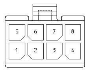
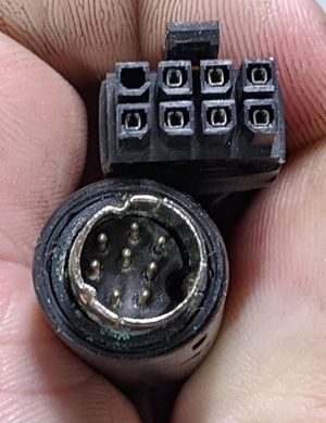
- 4x2 (8 pins)
- 3 mm pitch
- Head female, cable male
- Molex Microfit 3
- aka Amphenol Minitek Pwr™ 3.0 Series
- https://www.digikey.com/product-detail/en/amphenol-icc-fci/10132445-08LF/609-5283-ND/7590945
- aka Amphenol Minitek Pwr™ 3.0 Series
| Microfit 4x2 | Signal | Breakout cable color | Notes |
|---|---|---|---|
| 1 | Hall | Black | |
| 2 | Hall w/ cap | Red | |
| 3 | Drive | Orange | |
| 4 | Osc | Yellow | |
| 5 | Chassis ground | Green | N/C on main cable |
| 6 | Hall w/ cap | Blue | |
| 7 | Drive | Violet | |
| 8 | Osc | White |
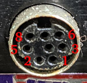
| Microfit old | Microfit
correct |
mini-DIN | Signal | Note |
|---|---|---|---|---|
| 1 | 4 | 1 | ||
| 2 | 3 | 2 | ||
| 3 | 2 | 8 | ||
| 4 | 1 | 7 | ||
| 5 | 8 | 3 | ||
| 6 | 7 | 5 | ||
| 7 | 6 | 6 | ||
| 8 | 5 | N/C |
| Microfit | mini-DIN | Signal | Note |
|---|---|---|---|
| 1 | |||
| 2 | |||
| 3 | |||
| 4 | |||
| 5 | |||
| 6 | |||
| 7 | |||
| 8 |
Motor on mini-DIN
- 1: drive motor +
- 3: drive motor -
- 7 V
| Microfit old | Microfit
correct |
cpc | Signal | Note |
|---|---|---|---|---|
| 1 | 4 | 8 | ||
| 2 | 3 | 6 | ||
| 3 | 2 | 1 | ||
| 4 | 1 | 4 | ||
| 5 | 8 | 5 | ||
| 6 | 7 | 3 | ||
| 7 | 6 | 2 | ||
| 8 | 5 | N/C |
Tach board
- Adapts 8 pin to 4 pin
- Includes cap + 4 pin SMD component (489, probably hall effect sensor)
- Must interface to those two red things I was confused about...looks like they have magnets on the end
- Minitek 4x2
- 4: 4x1.1
- 3: 4x1.3
- 2: hall, cap
- 1: hall
- 8: 4x1.2
- 7: 4x1.4
- 6: hall, cap
- 5: chassis ground
- 4x1
- 1: osc
- 2: osc
- 3: drive
- 4: drive
Test primary machine motor via 4x1
- drive: 10.2 R
- osc: 5.6 R
- *** out of spec
- consistent with a failed motor
failed motors appear to be caused by carbon buildup from brushes. They will fail very quickly if you operate them even close to their rated voltage. I was able to disassemble and blow one out to fix it. Now it runs at about 12.22V @ 350 mA. Current went down over time, maybe was 500 mA initially
Lets try another... initially 12.22V @ 1.25 A. Visible smoke. Rotor very dirty...should have cleaned other rotor. After cleaning dropped to 12.22V @ 1.1A and then rose up. Hmmm. Clean between rotar contacts. Success! Now 12.21 V @ 153 mA! Significant improvement! 9.6 ohm now
Back to original motor. Cleaned, now drawing 12.21 V @ 0.180 mA. Seems pretty concrete: needs to be cleaned, especially between rotar contacts. Try 18.86 V @ 197 mA. 9.6 ohm
Try osc motor. Didn't try running initially for fear of damaging. After cleaning (worst of all motors so far) 12.19V @ 175 mA. Current seems to be going down as well. 12.19 V @ 200 mA installed. However system is still not turning it (ie its not applying voltage). Other motor is about the same (even though it wasn't cleaned).
Osc 9V on 8 pin. Osc motor being driven at 1.3V. Maybe power supply is failing? Motor current via benchtop PS seems okay to me. Cross strapped channels and verified drive channel can drive either drive or osc, but osc cannot drive either channel. Probably need to open the unit up
McMaster misc
2020-01-14
- Win cross sectioning kit
2020-02-20
- Order sample holder
- Order replacement tubing
- Later found I had some spare, but meh can use for other projects
2020-05-06
- Measure grommets
- 23 mm diameter
- 11.5 mm high (0.45")
- 6.5 mm center
- Measure hole
- 25.3 mm diameter
- Grommet must be less than this
- ~9.15 mm high (0.36")
- Grommet must be higher than this
- 25.3 mm diameter
- Bolts
- 1/4-28 IIRC
- Around 6.25 mm OD
- Options
- https://www.mcmaster.com/90131a102
- Abrasion-Resistant Cushioning Washer
- for 1/4" Screw Size, 0.25" ID, 0.75" OD
- 0.110"-0.140" high
- Need: 12
- https://www.mcmaster.com/9540K914
- Heavy Duty, SBR Rubber, 15/16" OD, 1/2" High
- 3/8" ID
- Ned: 3
- https://www.mcmaster.com/90131a102
McMaster newer
S/N 568
Hermitage: Allvia Sunnyvale? Not sure if they are still in business
2019-12-19
- Submitted offer. Negotiations failed
2020-02-19
- Seller accepted offer (was firm at old offer). Local pick up
2020-02-232
- Swap DRO from spare to primary machine
- Replace rusted micrometer
2020-02-23
- Observe osc motor is not moving
- Observe osc doesn't have slit like spare to keep in place...how is it supposed to work?
- Is this a DRM thing of sort where they didn't supply the right adapter if the user didn't purchase osc option?
- ie the motor was intentionally disabled and also mechanically hindered
McMaster older
???
- Won a few lots of parts TechPrep heads
- Goal: combine into one good head and mount on SBT machine
2019-03-20
- Try to get old TechPrep base. Negotiations failed
2019-12-20
- Won old TechPrep base machine. Change plan from retrofitting SBT machine to actually fitting on this machine
- Without reference machine a little difficult to piece together
- Machine filthy. Significant cleaning
2020-02-23
- Used reference machine to greatly accelerate repairs
- Made cable to hook up head
- E1.43 (error code?) persists, but machine seems to work fine
McMaster 2020-06-07
Test1: spare arm
Testing out arm on the table. I believe it was mounted on the newer machine
Goals:
- Understand osc motor
- Check motor health
- Clean arm. Some precision surfaces are dirty
Motor current tests
- Osc
- yellow +, white -
- 7.6 V @ 175 mA
- went down to 160 mA after a bit
- Motor not loaded (coupler removed from top)
- Spinning CCW
- Drive 15.0 V
- orange+, violet -
- Motor not loaded (removed rubber ring)
- 7.6V @ 150 mA
Conclusions:
- Pinout table is correct
- Motors work and are in spec
Test2: production arm
Osc
- 7.6V 2 180 mA under load
- Shows: motor is fine, I probably don't have the cable correct
Drive
- 7.6V @ 160 mA no load
- 170 mA w/ rubber attached
Conclusion: found loose wire.Take this as an opportunity to make a proper cable...either a new one or solder the existing one


